In July of 2014 I was invited by Mike, KI6OID, of the Red Cross here in the Bay Area, to help with a unique HF (low frequency) antenna build. He and I have a mutual friend, Suresh (W6KTM), who started a non-profit organization in 2007 to create what’s called Radio Mala. Their goal is to implement technological leaps in communication in India to help protect and provide relief to its population in the event of natural disasters, which the area is very prone to on what seems to be a regular basis.
Radio Mala’s first step has been to establish what’s called a “Repeater Network” in Nepal, India. More specifically, Kathmandu Valley. Repeater Networks are very common in America and many other countries, but would be considered a technological leap in Kathmandu Valley. Once deployed, the repeater network serves as an “offline” communications network in the event of a natural disaster. By offline I mean it works when cell phones and the Internet do not. To better understand repeater networks, check out Radio Mala’s website.
Suresh asked Mike and I for a compact HF antenna solution capable of communicating within a 25 to 300 mile radius within and outside of the Kathmandu Valley. This is a very common need in the event of a natural disaster: you need point-to-point consistent communications within a very defined radius or region. This would give you access to those immediately affected by the tragedy, and access to the outside world when nothing else exists to facilitate the urgent need. This particular radius is also unique because around the Kathmandu Valley is mountains. To jump straight to the point, not many antenna designs can get over mountains and onto the other side, but there is one communication technique that offers a real possible solution. This technique is used regularly by the military in field operations. It’s called NVIS: Near Vertical Incidence Skywave. In the radio wave (RF) world it’s common to bounce RF transmissions of a certain frequency range off the atmosphere and back down to the surface of the earth. The NVIS technique challenges the transmitting station to orient its antenna in such a way where it transmits a signal almost straight up (near vertical) to the atmosphere. If done correctly, the signal is then reflected back down at a similar sharp angle without any signal degradation on the receiving end. Illustrated here…
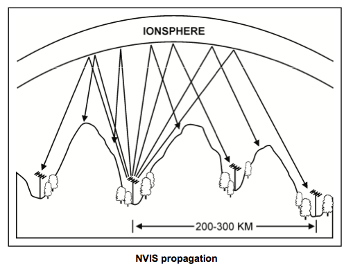
Pretty self-explanatory. Our challenge was to design a compact antenna to suit this very specific need. We chose the 7 Megahertz (MHz) frequency. This is the highest tolerable frequency for the NVIS technique. Any higher in frequency and the transmission will go through the atmosphere. Any lower frequency and the size of the antenna grows substantially larger and beyond our needs. Saving you from further boring explanations, please accept these last two points as reasonably true!
Mike found an antenna, but its design is very difficult! In fact, so difficult we had to assemble a 3-man team, which has grown into a 5-man team as I write this today. Two of the members have wickedly impressive electrical backgrounds. One of which wrote a paper on our antenna, which I’ll present at the bottom of this blog entry. And while we were building the antenna Suresh was visiting Nepal for some business and family. He was kind enough to bring us all Nepal hats with our call signs embroidered on the sides. Spiffy!
Let’s get to the antenna already. Introducing the Helical Loaded Magnetic Loop Antenna.

Pretty cool, huh?! Comes with it’s own flux capacitor 😉
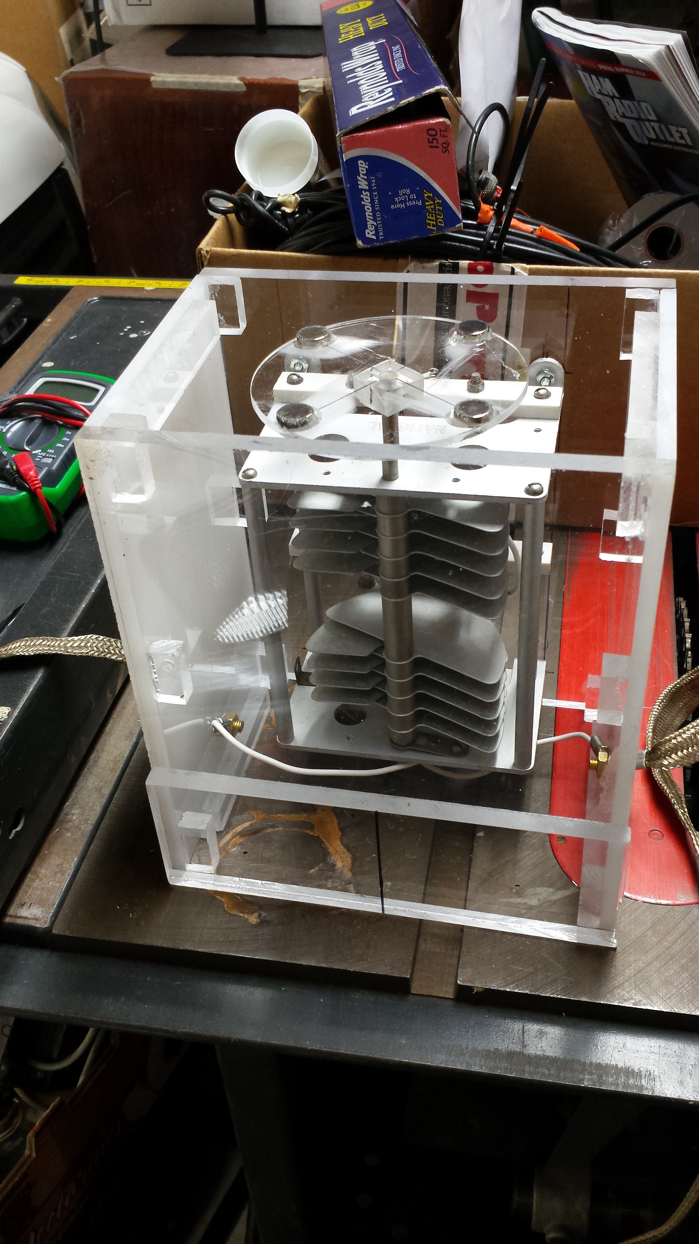
Contrary to popular belief, no, you can’t power up the antenna and stand in the center for direct teleportation to the year 1988.
The design comes from a gentleman in Arizona. His name is Rich, callsign K8NDS, and he’s been making these for himself for several years. He’s documented them quite extensively. Our version ended up being a poor man’s version by comparison. It was recently referred to as a “plumbers antenna.” But, the results that we’ve witnessed with this antenna are eyebrow-popping impressive.
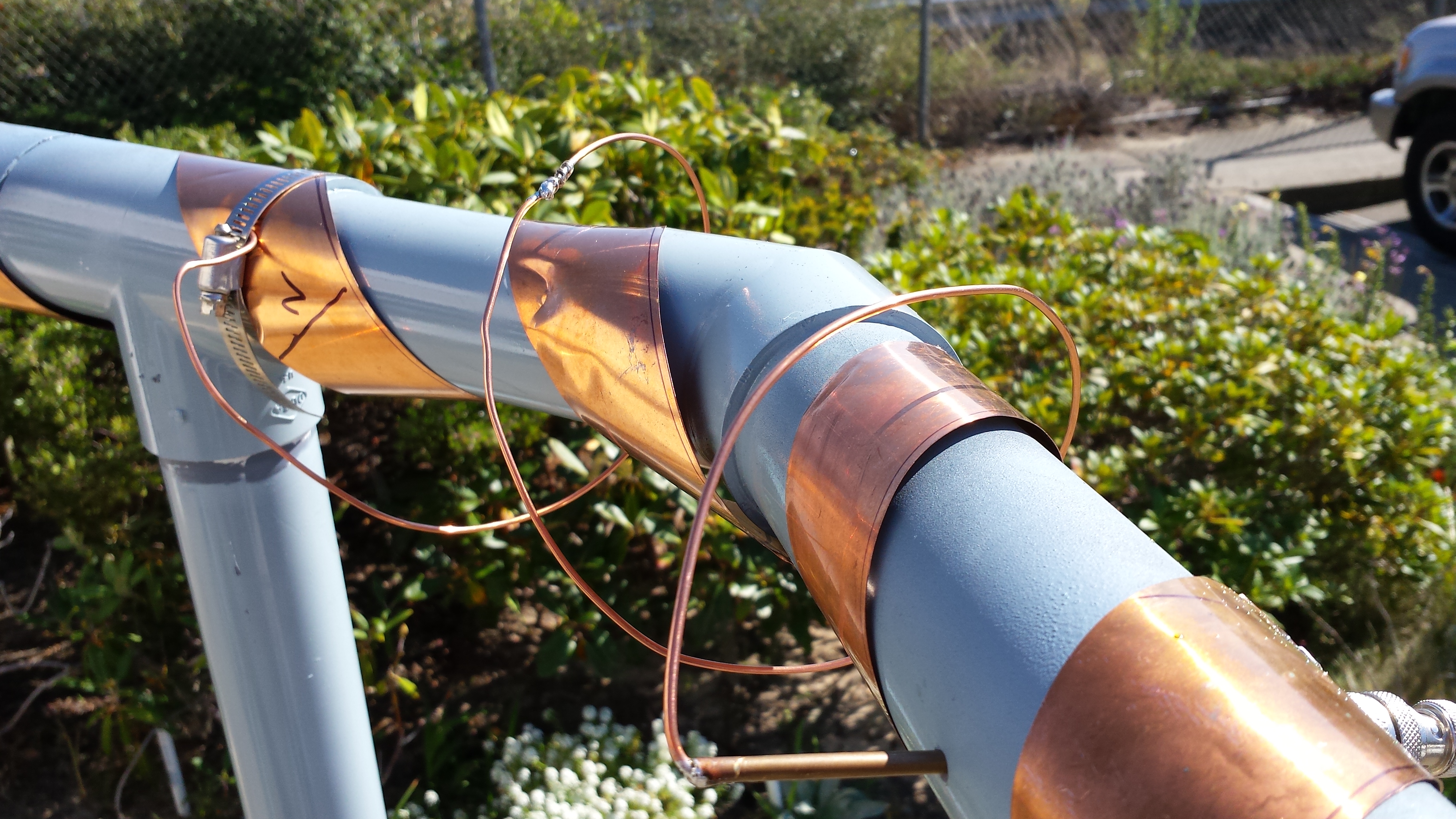
I could write about this antenna for days, but I won’t. Instead I’ll get back to its intended use: Kathmandu Valley, India. Sadly, this particular design — though it works as intended — cannot be effectively and safely replicated, implemented, and maintained in India. The antenna is very sensitive. The slightest touch and it has detuned itself. A 10-degree temperature swing outside and it has detuned itself. Not to mention when you transmit at 50-100 watts you’re generating around 7,000 volts of electricity in the capacitor. All of these things, and more, create a very unstable communication solution. What’s needed is the opposite.
What I learned from building this antenna has been incredible. Getting to meet and hang out with what I consider professional athletes of the modern electronics field was nothing short of inspiring. One literally hangs on every word.
Brian’s paper below.

Leave a comment